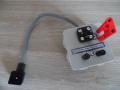
Dismantling and inspection

of the pilot operated pressure relief valve

1- Role

The role of the main pressure limiter is to protect the pump from overpressure.

The pump generates a flow that must be directed at all times:

     - To the hydraulic receivers.

- To the tank using a directional valve.

- To the tank using a pressure relief valve.

2-Identification

In the hydraulic diagram, the pressure relief valve is located between the pump and the distributor.

Physically it can be located:

          - Directly on the pump (example: option on gear pumps).

- Between the pump and the distributor (example: on a manifold block).

- On the directional valve (example: inlet plate of the mobile type distributors (6/3 or 4/3 LS)).

Limiteur de pression a action pilotee 1

In the picture above, a pilot-operated pressure relief valve type CETOP 3 (ISO) or NG6 (DIN).

The simplified diagram of the pressure relief valve is riveted to the block.

The assembly is sandwiched between a manifold block and a directional valve. Four O-rings will seal between each slice and will be assembled with four screws (CHC M5 12.9).

Limiteur de pression a action pilotee demonte 2

In the picture above, the detailed symbol (Fig. A) of the pressure relief valve is representative of the pressure valve mechanism.

We distinguish from left to right:

          - The poppet valve (item 3) with integrated jet (item 5).

          - The non-adjustable spring of low stiffness (item 4).

          - The metal block of the valve.

          - The poppet valve (item 6).

          - The adjustable spring of high stiffness (item 7).

          - The adjusting screw (item 8).


3-1 Power stage

Limiteur de pression a action pilotee 2 2
 

It consists of a power stage that directs the flow to the tank.

There is a spring of low stiffness not adjustable and a poppet valve with a jet held in place by a circlip (photo above).

The jet ensures the proper functioning of the pressure relief valve.

3-2 Pilot stage

  • Hydraulic hotline

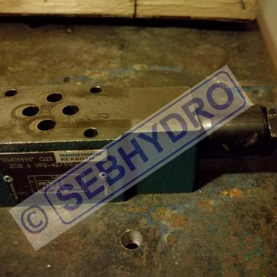
    Résoudre vos problèmes hydrauliques rapidement HOTLINE (Réponse rapide) Résoudre...

    1 320,00€ inc. tax

    Details
Limiteur de pression a action pilotee 3 2

The superimposed pilot stage controls the opening of the power stage.

There is a spring of high stiffness adjustable and a poppet valve held in place in its housing by a circlip (photo above).

A hole ensuring the internal drainage of the spring box.

An O-ring seals the outside of the assembly.

Limiteur de pression a action pilotee 5 2

A seal makes it possible to seal the cartridge between P (pressure) and T (return to the tank).

Pilot operated pressure relief valves are more sensitive to pollution than direct acting pressure relief valves.

Pollution is responsible for the majority of failures that make the pressure relief valve leaking:

      - The jet that gets clogged.

       - The defective seal ensuring the internal sealing of P to T.

       - A broken spring that no longer closes the valve (pilot stage or power stage).

5- Setting

     - Loosen the pressure relief valve.

     - Install a pressure gauge on the circuit (between the pump and the directional valve).

     -Switch the pump on at maximum speed.   

    - Activate a movement to put a cylinder in mechanical stop.   

    - Tighten the pressure relief valve by checking the rise in pressure on the pressure gauge.

     - If the cylinder moves, stop the adjustment.

     - Once the cylinder stops, finish the adjustment.


Add a comment

Anti-spam