Technical sheets


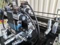
Test a coil of a hydraulic directional valve


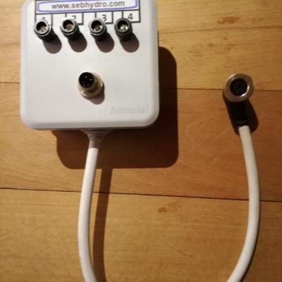
Test box for 3- and 4-wire sensor
99,00€
89,10€ inc. tax
82,50€
74,25€ excl. tax
55,00€ inc. tax 52,13€ excl. tax
Details
55,00€ inc. tax 52,13€ excl. tax
Details
Hydraulic training : The basics Vol 1
55,00€ inc. tax 52,13€ excl. tax
Details
Add a comment