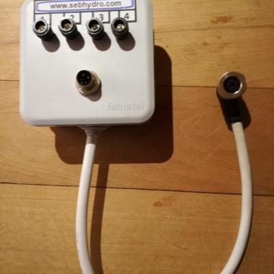
Test box for 3- and 4-wire sensor
99,00€
89,10€ inc. tax
82,50€
74,25€ excl. tax

0,00€ inc. tax 0,00€ excl. tax
Details
Hydraulic training : The basics Vol 1
55,00€ inc. tax 52,13€ excl. tax
Details1 - Why clean up ?
2 - When to clean up ?
3 - In what proportion to decontaminate ?
55,00€ inc. tax 52,13€ excl. tax
Details4 - The main standards related to pollution
5 - When to take an oil sample ?
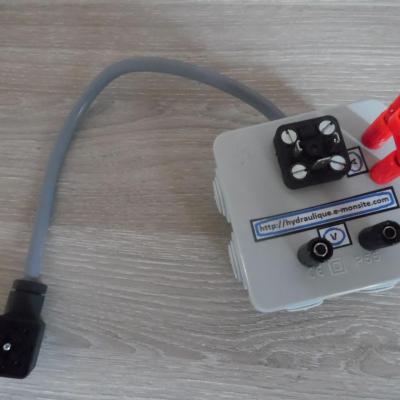
box for hydraulic coil test DIN EN 175 301-803-A (HIRSCHMANN GDM-séries)
99,00€
89,10€ inc. tax
82,50€
74,25€ excl. tax
6 - How to take an oil sample ?
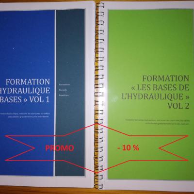
Formation hydraulique "les bases" vol 1&2
110,00€
99,00€ inc. tax
104,27€
93,84€ excl. tax
55,00€ inc. tax 52,13€ excl. tax
Details
55,00€ inc. tax 52,13€ excl. tax
Details
55,00€ inc. tax 52,13€ excl. tax
Details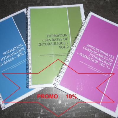
165,00€
148,50€ inc. tax
156,40€
140,76€ excl. tax
7 - Particule size

8 - Pollution classes

9 - Correspondence between standards
13 - Counting methods

1 320,00€ inc. tax 1 100,00€ excl. tax
Details11 - Recommendations
12 - Description of an oil analysis

Add a comment