Operation

 3-way flow regulator

1-The flow limiter

Jet, restrictor, restriction, speed reducer ... are all terms corresponding to the flow limiter.

Do not confuse with the flow regulator which is another hydraulic component.

There are two types of flow restrictors:

     - Unidirectional (the flow is reduced only in one direction of passage).

     - Bidirectional (the flow is reduced in both directions).

There are several ways to install a flow limiter:

      - Serial at the receiver's inlet.

       - In series at the exhaust of the receiver (pay attention to the overpressures caused by the differences of sections of the cylinders).

      - In parallel, drifting from the oil to the tank.

In all cases, it is found that the flow passing through a simple choke will not be preserved if the loads of the receivers vary.


2- Flow regulator

The flow regulator keeps a constant flow regardless of the load of the receiver.

There are two types of flow regulator:

     - 2-way flow regulator.

     - 3-way flow regulator.

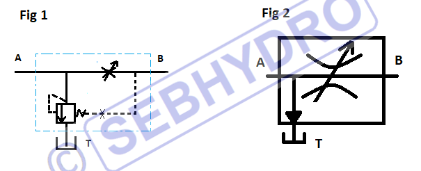
We can find two symbols:

- The simplified symbol (Fig. 2).

 
Schema regulateur de debit 3 voies 2

On the simplified symbol, does not appear:

     - The pressure balance.

     - Hydraulic steering on the spring.

     - The jet that stabilizes the valve.

They are replaced by a simple arrow.


3- 3-way flow regulator: closed valve

Regulateur de debit 3 voies stand by 1
 

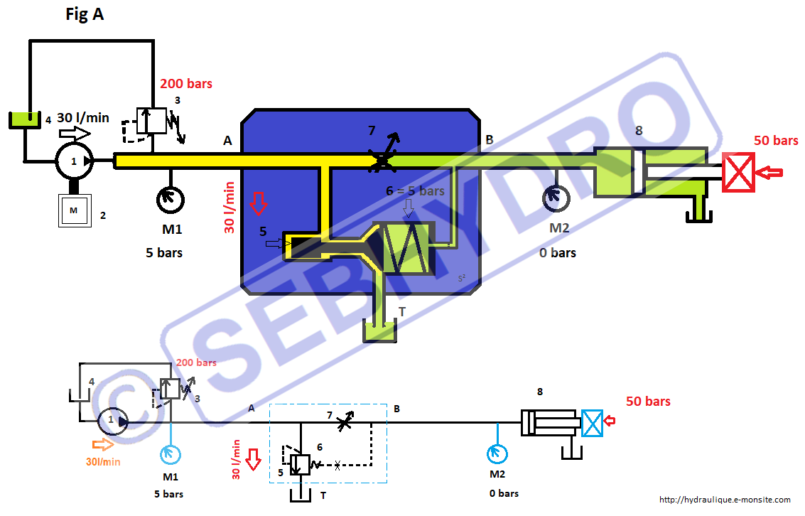
The diagram is representative of the mechanics. As the name suggests, the 3-way flow regulator has three ports:

      - A: inlet of the valve.

      - B: outlet of the valve.

      - T: return to the tank.

balance is normally closed at rest and allows the oil to flow from A to T when the pilot pressure acting on the valve (item 5) reaches the value of the spring (item 6), to which will be added the counterpressure of steering taken behind the valve.

The spring (rep 6) is 5 bars and is not adjustable, its hardness is included depending on manufacturers between 2 and 10 bars.

The pump (item 1) driven by a heat engine (item 2) delivers 30 l / min. It is protected by a pressure relief valve (item 3) set at 200 bars.

The entire pump flow (30l / min) returns to the tank through the pressure balance at a pressure of 5 bars.

This pressure is created by the spring (item 6) of the valve (item 5). No back pressure is added to the hardness of the spring since the valve (item 7) is closed.

The waiting or stand-by pressure is 5 bars in M1.


4- 3-way flow regulator: cylinder output

  • Hydraulic hotline

    Résoudre vos problèmes hydrauliques rapidement HOTLINE (Réponse rapide) Résoudre...

    1 320,00€ inc. tax

    Details
Regulateur de debit 3 voies fonctionnement 1

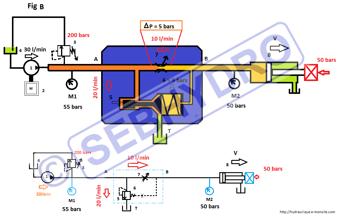
We open the valve (item 7) of the flow regulator, the stand-by pressure (5 bars) is looped back against the spring (item 6) and closes the pressure balance. The oil from the pump is compressed and the flow dosed by the opening of the valve (item 7) moves the cylinder. The pressure created by the load is established on M2 at 50 bars.

This same pressure is brought back in backpressure on the spring (item 6). The poppet valve has an opening value of 5 bars of spring + 50 bars of back pressure. 10 l / min goes to the cylinder, the pump excess flow (20 l / min) returns to the tank through the pressure balance by raising the poppet valve (item 5) to 55 bars found in M1.

A pressure difference (ΔP) of 5 bars is observed at the limits of the restriction.


5- Flow regulator: cylinder output with load change

Regulateur de debit 3 voies en regulation 1

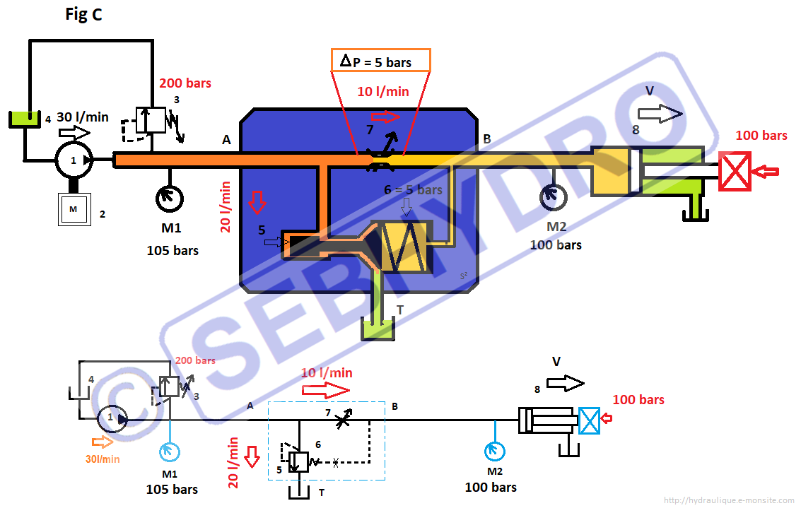
The cylinder load increases to 100 bars in M2. Instantly the backpressure in the pressure balance also increases to 100 bars and has the effect of hardening the spring (item 6) forcing the excess oil to return to the tank by lifting the poppet valve (item 5) at 105 bars found in M1.

It is observed that the pressure difference across the restriction is always 5 bars. The flow will remain unchanged and the cylinder will come out at the same speed.


6- 3-way flow regulator: cylinder in mechanical stop

Regulateur de debit 3 voies verin en butee 1

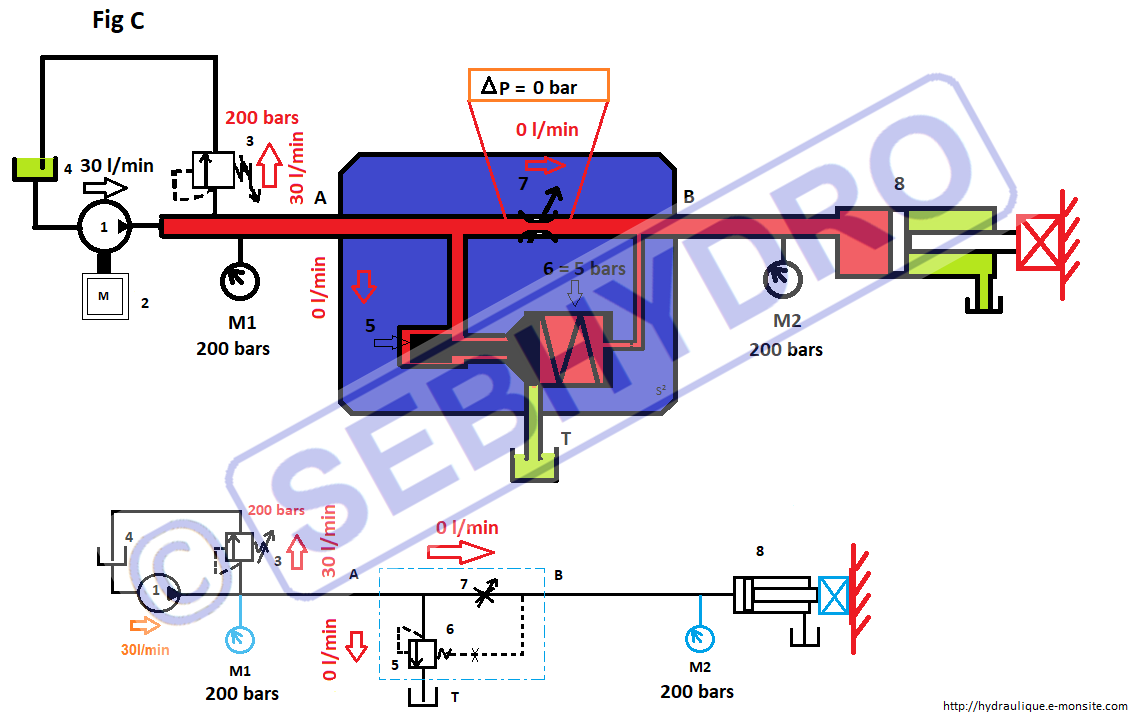
The cylinder reaches the stop, the pressure difference across the restriction vanishes, the pressure balance closes and cannot open. All the flow of the pump returns to the tank by the pressure relief valve. We find 200 bars in M1 and M2.


Follow on Facebook

Find other sheets


Add a comment

Anti-spam