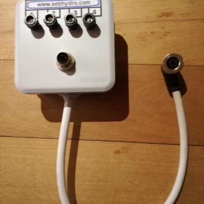
Test box for 3- and 4-wire sensor
99,00€
89,10€ inc. tax
82,50€
74,25€ excl. tax
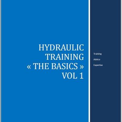
Hydraulic training : The basics Vol 1
55,00€ inc. tax 52,13€ excl. tax
Details
2. The alternator

55,00€ inc. tax 52,13€ excl. tax
Details3. Charging principle

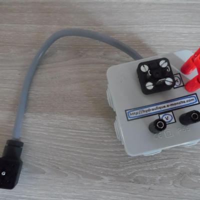
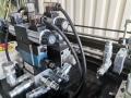
box for hydraulic coil test DIN EN 175 301-803-A (HIRSCHMANN GDM-séries)
99,00€
89,10€ inc. tax
82,50€
74,25€ excl. tax
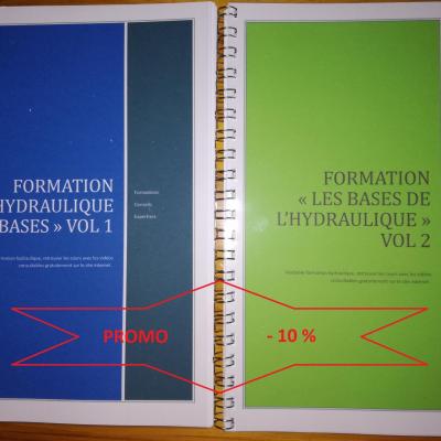
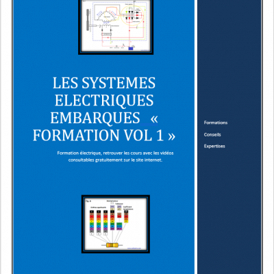
Formation hydraulique "les bases" vol 1&2
110,00€
99,00€ inc. tax
104,27€
93,84€ excl. tax
55,00€ inc. tax 52,13€ excl. tax
Details
4. Alternator operation


55,00€ inc. tax 52,13€ excl. tax
Details
55,00€ inc. tax 52,13€ excl. tax
Details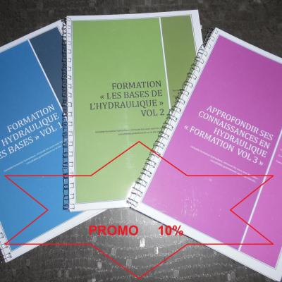
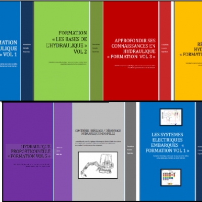
165,00€
148,50€ inc. tax
156,40€
140,76€ excl. tax


55,00€ inc. tax 52,13€ excl. tax
Details
55,00€ inc. tax 52,13€ excl. tax
Details

5- Malfunction
Add a comment